
(originally by Colorado Tom on head-fi; annotations and formatting mine)
The following description is specific to the STAX 006t II vacuum tube output driver unit but much of the procedure is similar for any of the STAX tube units (SRM-T1, SRM-T1S, SRM-T1W, SRM-006t and SRM-006tA/II)
WARNING – DON’T BE STUPID. If you cannot read English very well, are uncomfortable around high voltages, describe yourself as “all thumbs”, “ham-fisted” or “awkward” and have never worked inside of any electrical component that has potentially lethal voltages DO NOT attempt any of the procedures listed below. Do yourself and your equipment a favor and find someone who can, or take a copy of this to a local audio/video repair shop and ask them if understand what is being described and can they can do it for you.
Disclaimer – I make no warranty and accept no responsibility for suitability of any materials listed below. I assume no responsibility or liability for errors or inaccuracies. Reader accepts all responsibility for any and all results obtained. Use of any supplied materials constitutes acceptance and understanding of these disclaimers.
STAX clearly states on the Operating Manual for the 006t II that “This product operates with a high voltage. It is extremely dangerous to attempt to dismantle or modify the unit in any way, and under no circumstance should any such attempt be made.” What I have done has clearly violated the manufacturer’s warranty – YOU HAVE BEEN WARNED!
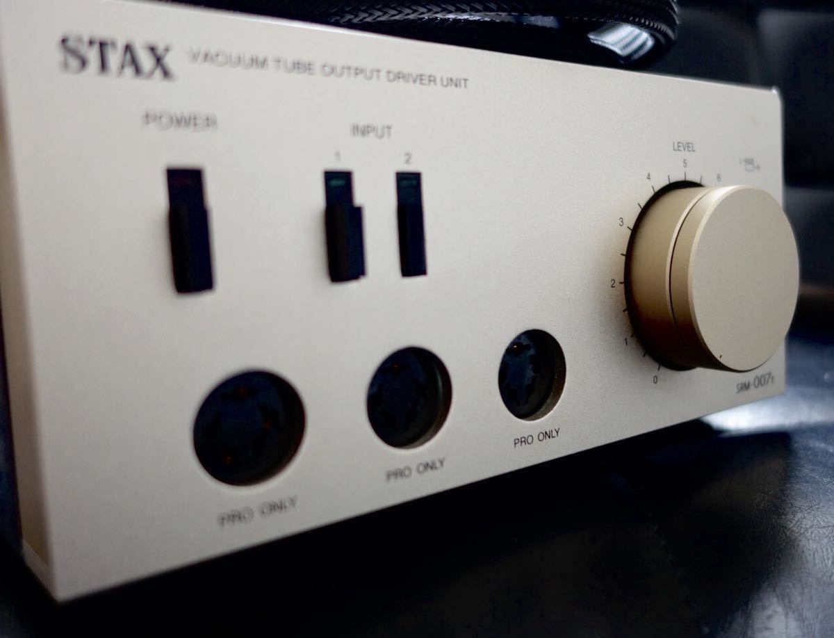
What follows is a description of how I changed and adjusted the tubes in my personal STAX 006t II vacuum tube amplifier.
The tools I used were a Philips screwdriver (to remove the cover), an insulated (plastic) slot head screwdriver (to adjust the internal potentiometers), and a good quality multimeter that is set to measure volts .... NOT AMPS!
(personally, I used the 2000mV measurement)
Procedure I used:
I disconnected the headphones, unplugged the unit from the wall power, and using a Philips screwdriver, removed the four screws that hold the top.
I removed the two 6FQ7 (6CG7) tubes and replaced them with the new tubes (that were checked with a tube tester prior to insertion in the unit).
(small note: a small batch of SRM-007t came with 8FQ7/8CG7 vintage GE tubes, and should be replaced with that tube type instead)
With the cover still off I plugged in and powered up the unit leaving it on for about and hour to stabilize. WARNING – at this point the cover is off and the unit is powered. I NEVER leave an electrical unit in this state unattended for any reason.
Below is a diagram of the earspeaker connector as it would appear if you were looking at it from the front of the unit. There are two of these connectors with the words “PRO ONLY” above them. They will not have "L+", "L-", "R+".... those labels identify the holes for the purpose of the discussion below.
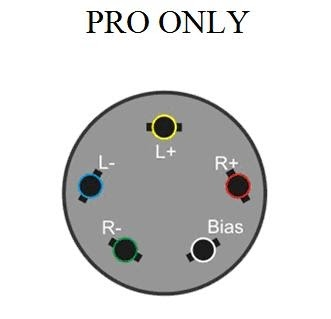
WARNING - DO NOT under any circumstances put a probe into the socket shown on the bottom right labeled above as “Bias”. In fact, I covered it with a small piece of tape so that I wouldn’t have the possibility of an accident that could damage the unit or myself.
(Bias is what powers the headphones, and on pro outputs like above it's a gigantic 580V; you'll fry the multimeter and possibly other things)
I set my multimeter to measure volts and inserted the positive probe into the slot shown above labeled “L+” and inserted the negative probe into the slot labeled “L-”. At this point I was measuring dc balance. My first measurement was in the 6 volt range, the reading could have been higher or lower, the goal is to get it under 1 volt. To adjust the value I used a plastic (NOT METAL) slot head screwdriver and adjusted the potentiometer labeled “TVR1” for the left channel. The potentiometer is EXTREMELY sensitive and the meter reading will have a tendency to drift around a bit. With some effort I was able to get the reading stabilized at about 0.250 volts.
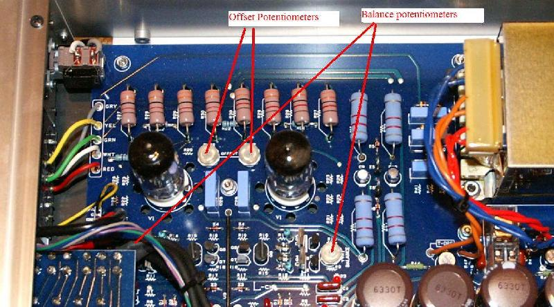
I then removed the negative probe from the slot labeled “L-“ and attached the probe to the ground post labeled “GND” at the back of the unit. At this point I was measuring dc offset. Initially, the dc offset was around 1.5 volts. Again, the object was to get the dc volts under 1 volt. To adjust the value I used a plastic (NOT METAL) slot head screwdriver and adjusted the potentiometer labeled “TVR2” for the left channel. Again, the potentiometer is EXTREMELY sensitive and the meter reading will have a tendency to drift around a bit With some effort I was able to get the reading stabilized at about 0.090 volts.
I confirmed that the dc balance was still below 1 volt by removing the negative probe from the ground post and re-inserting it into the slot shown above labeled “L-”. If needed I could have adjusted the dc balance again and lowered it under 1 volt, but it still measured close to 0.250 volts. This process of going back and forth between the adjustment of dc balance and dc offset could have happened several times.
(this whole process takes a lot of going back and forth, and the values drift a lot with even the slightest turns; just be patient and occasionally let the readings stabilize. you can ignore the TVR3/TVR4 pots on quad tube amps; I believe they're for unmatched tubes and should already be adjusted properly)
At this point the left channel adjustments were complete. I followed the exact same procedure for the right channel with similar results for the measured and adjusted voltages.
With both channels adjusted I turned off and unplugged the unit. With the unit unplugged I attached the top using the four screws and then plugged in the unit into the wall power and I was done.
A lot of old documentation on STAX stuff is slowly dying out on the internet; this little tutorial was actually already reposted once after the images were no longer being hosted. In the interest of preservation for a necessary and somewhat complicated procedure, I'm reposting this article, with my own annotations from my personal attempt at rebiasing an old SRM-007t.